Loading
Loading
 Cutting
cncKad cutting turns CAM files into NC code for your cutting machine. In a few clicks you are able to generate efficient programs while optimizing material utilization and machine runtime.
The cutting solution can be influenced by factors such as head, gas, lens, corner treatment, cutting optimization, and MicroJoints. You can modify the proposed parameters and edit the cutting tables as required.
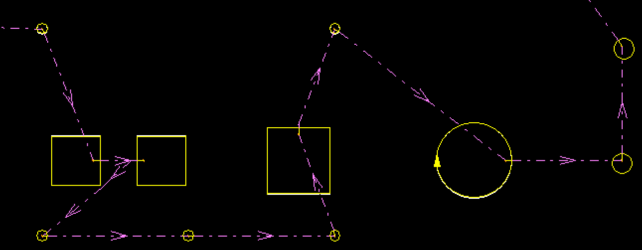
You can easily control common line cutting, cutting part-by-part, cutting order, and any other specific way of processing the sheet.
cncKad always optimizes the chosen methods to minimize the production time, taking machine capabilities and limitations into account. The post-processor then converts these actions into efficient NC programs.
 Automatic Cutting
Based on predefined rules, Automatic Cutting solutions are influenced by factors such as lead-in, corner treatment, part handling, cutting optimization, MicroJoints, material, and thickness.
AutoCut processes parts efficiently and consistently, saving time and giving standard solutions for production. You can control all the parameters in one place:
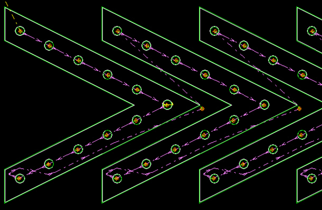
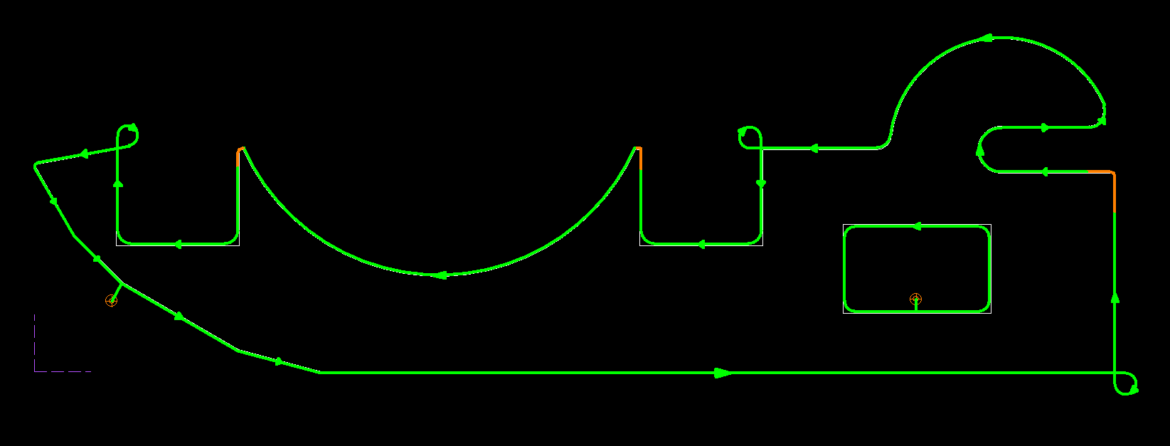 This part was processecd using loops, rounding, and cool down (marked in brown)
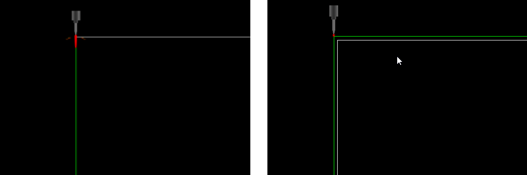
 Beam Compensation Solutions
cncKad provides two types of beam compensation solutions for laser or plasma machines:
 Cutting Technology Tables/Import External Tables
The Cutting Technology Tables allow you to define, view, and edit cutting technology parameters. The tables contain charts that cover all aspects of a material’s cutting:
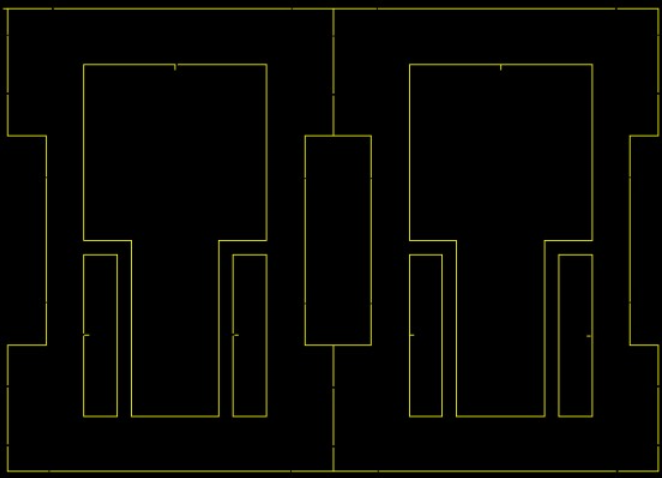
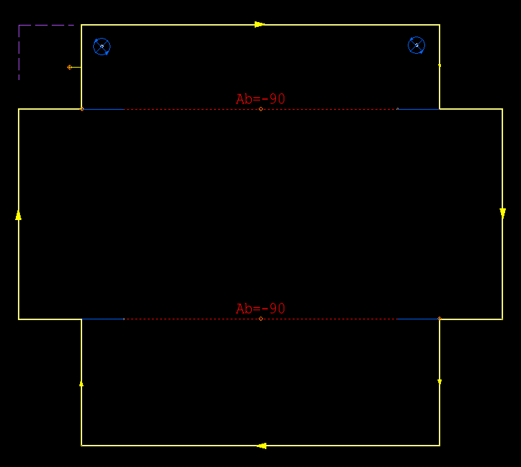
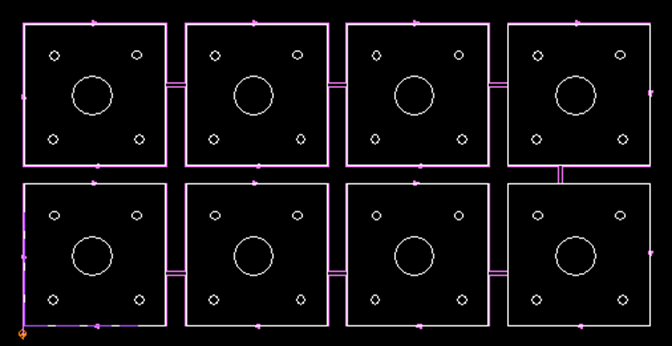
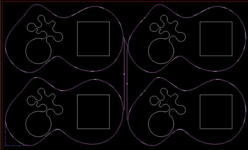
Common Cuts
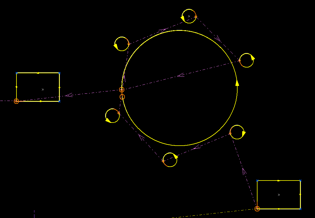
cncKad’s common cut feature allows you to process the edges of two adjoining parts with the same cut, thereby saving material, cutting gas, and time. Instead of cutting each part individually, cncKad checks if adjacent part contours are at a distance that enables using common line cutting. This powerful feature saves material, cutting gas, time, and also avoids the need to pierce the sheet again.
Advanced TechnologiescncKad supports advanced technologies, compatible with your cutting machine. Advanced cutting technologies enable the full use of machine capabilities.
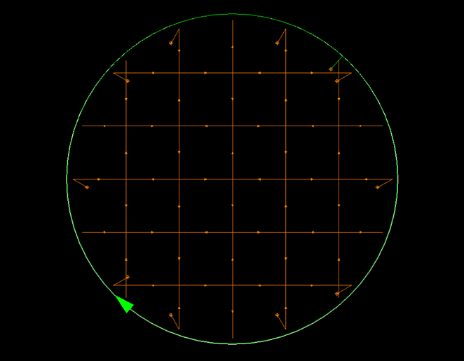
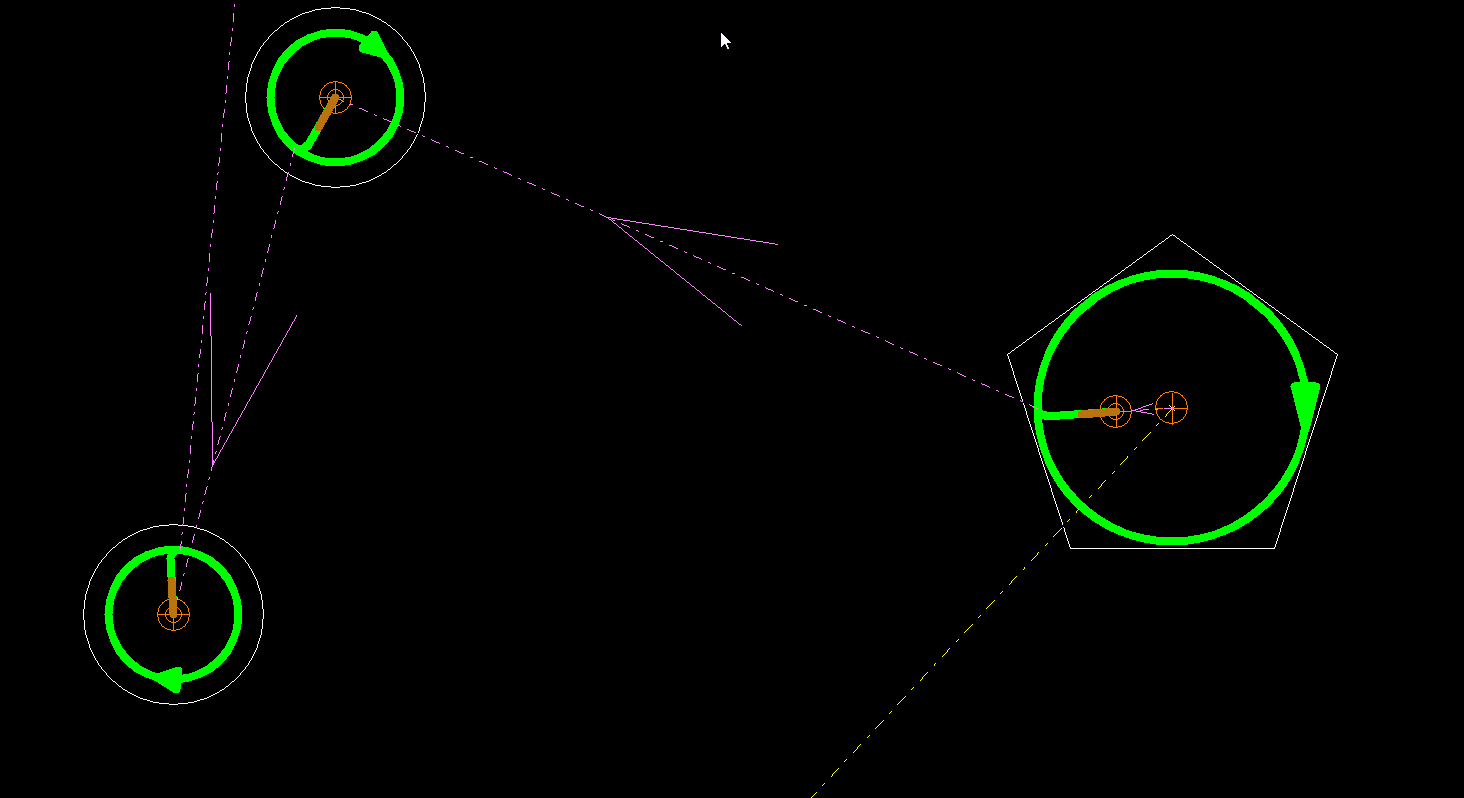
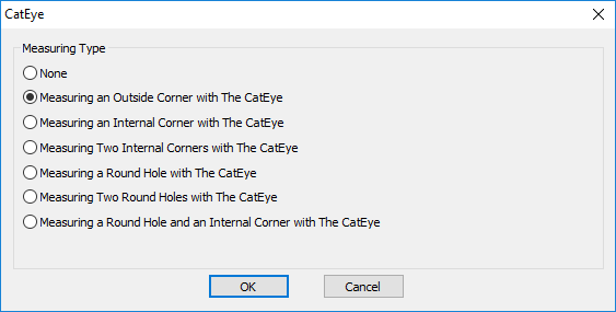 The picture shows options for measuring the sheet
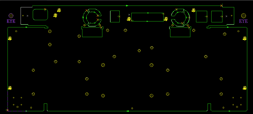 The picture shows how CatEye measures two round holes
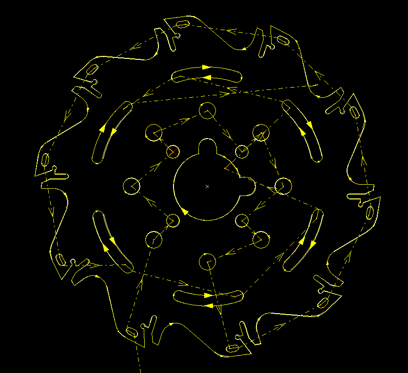
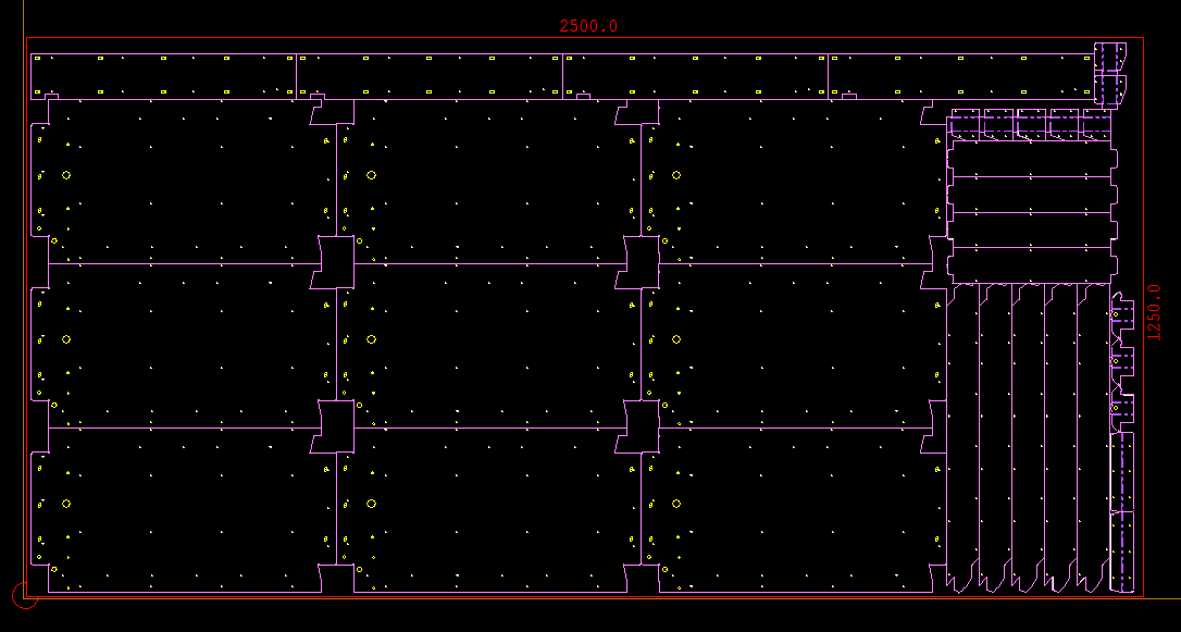
 Tool Path Optimization
cncKad provides a powerful tool path optimization function for improving the efficiency of the cutting tool path. You can adjust the processing path of the holes in the part and on the part’s outer contours.